Views: 451 Author: Lucian Publish Time: 2026-09-24 Origin: Site


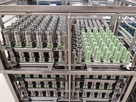
A drawing can show generous mesh openings and still say nothing about whether a sealing face, cross-hole or internal shoulder will be cleaned. Once the basket is loaded, the process sees a combined structure made from the frame, supports and parts. When that structure hides a critical surface, the result can be rejected parts, repeat cleaning and lost production time.
Industrial cleaning basket blind spots can form wherever a support or another part covers the surface that needs cleaning. We start with the affected face, bore or recess, then examine its position in the loaded basket. A more open mesh helps only if liquid can reach that feature and loosened contamination can leave.
A basket is part of the cleaning process because it fixes where every component sits. The required access route changes with the way the equipment cleans, so one generic “free-flow” claim cannot cover spray, immersion and ultrasound equally.
Directional access
Liquid entry and air escape
Immersed exposure
A process engineer usually knows which surfaces decide acceptance: a sealing land, bearing seat, thread, oil gallery, electrical contact area or coated face. Those surfaces should be marked on the part drawing before AUKE decides whether the basket needs bulk loading, parallel dividers or individual positions.
With the part drawing and loaded photographs, we can identify support positions that cover a critical face or bore. We compare alternative orientations before fixing the layout, and we can document the proposed contact points on the basket concept for discussion. Four details in the brief help us judge where supports may interfere with cleaning.
Nozzle direction, immersion fill route or relevant ultrasonic exposure.
Fixed, tilted, rotated, oscillated or transferred between positions.
Permitted supports, prohibited contacts and neighboring components.
Air, loosened soil, chips, cleaning liquid and rinse water.
Basket open area is normally calculated from wire or perforation geometry. It does not account for a row of flanges placed face to face or cylindrical parts laid across each other's cross-holes. Larger mesh openings cannot expose a surface covered by another component.
Part pitch should therefore be measured in the direction that matters to cleaning. Two components may have generous side clearance while their projected profiles overlap directly in front of a spray path. In immersion, the same pitch may be acceptable if liquid and air can exchange freely around the critical feature. The process decides which clearance is useful.
Extra capacity can increase repeat cleaning
Adding another row may improve pieces per cycle while reducing cleaning exposure enough to create rework or a second cycle. The useful comparison is accepted pieces per hour, not the nominal number loaded into one basket.
Every fixture must touch the part. AUKE uses the marked critical surfaces and allowed-contact zones to decide where that contact can occur. A shaped wire may follow a non-critical diameter. A narrow saddle may locate a component below a sealing face. A keyed support can hold a bore at a venting angle instead of letting it rotate randomly.
The smallest contact is not automatically the best contact. Reducing support width raises local pressure and can make the load less stable. Changing the part angle can increase loaded height. Wider spacing protects access but reduces capacity. We compare those effects before converting the concept into a production drawing.
The load path still governs the structure. Wire diameter, joint location and loaded weight determine whether a shaped support remains stable. A perforated support also needs an agreed sheet thickness, hole size and edge distance. Bending tolerance and weld distortion must be controlled wherever they can move a support into the required clearance.
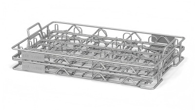
Repeated wire supports can hold parts at defined contact points. Their shape and spacing must follow the part drawing: a support that locates the part securely may still cover a face that needs cleaning.
Bending and welding can change that position. Measure the finished support height, pitch and clearance against the agreed drawing; overall basket dimensions alone will not reveal a misplaced contact.
The sheet does not need finished basket dimensions. Its purpose is to stop a critical cleaning requirement from disappearing inside a general request for mesh size and capacity.
Define the clean surface before the basket
Send the part drawing, marked critical surfaces, cleaning action, allowed contacts and quantity target. We will compare orientations and support layouts, then identify the access dimensions that belong on the basket concept.
An empty basket can confirm dimensions, but cleaning performance needs a loaded trial. Use representative parts with the intended quantity, orientation, soil and production cleaning cycle. Inspect the specified surfaces using the customer's agreed acceptance method, including positions near rails and in the centre of the load.
Run the intended load in the customer's cleaning equipment with agreed process settings, and record the support position, part pitch and orientation. AUKE can use those results to refine the basket drawing. The basket must also retain every component through handling; a result that depends on operators arranging parts by eye will be difficult to repeat.
DESIGN TRANSFER
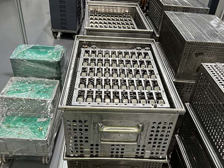
Individual locations give the drawing a stable reference for pitch, support height and orientation. They also let quality teams trace a problem to one position instead of treating the basket as an undefined bulk load.
When production does not require individual fixtures, dividers or orientation features can still provide the minimum repeatability needed by the process.
A successful sample is not enough if the next batch changes the relationship between part and process. AUKE places the access-defining dimensions on the controlled drawing: contact location, support height, part pitch, loading direction, orientation feature and any frame clearance that must remain open.
Production fixtures hold those relationships during welding where needed. Finished measurements use the functional references after forming and welding, not only the flat material dimensions. This connects the cleaning result to features that purchasing and quality teams can specify again.
No. It describes the basket material, not the complete loaded path. Supports, frames and neighboring parts can still close the route to a critical surface.
Not necessarily. Spray needs a directional approach, while immersion also depends on liquid entry and air escape. The basket orientation should be defined for the actual process.
Only when the overlap blocks a required cleaning route. A different angle, staggered layout or local support change may preserve access with less effect on quantity.
Send the part drawing, critical surfaces, allowed contact zones, cleaning method and direction, required quantity, part weight and current loading orientation.
Protect the route to every critical surface
Share the part drawing, marked critical surfaces, cleaning action, allowed contacts, quantity and loading orientation. We will compare support concepts, identify the access tradeoffs and define which dimensions the loaded trial must prove.
Discuss Cleaning AccessBy AUKE Engineering Team