Views: 0 Author: Lucian Publish Time: 2026-10-30 Origin: Site


AUKE / GEAR SHAFT CLEANING
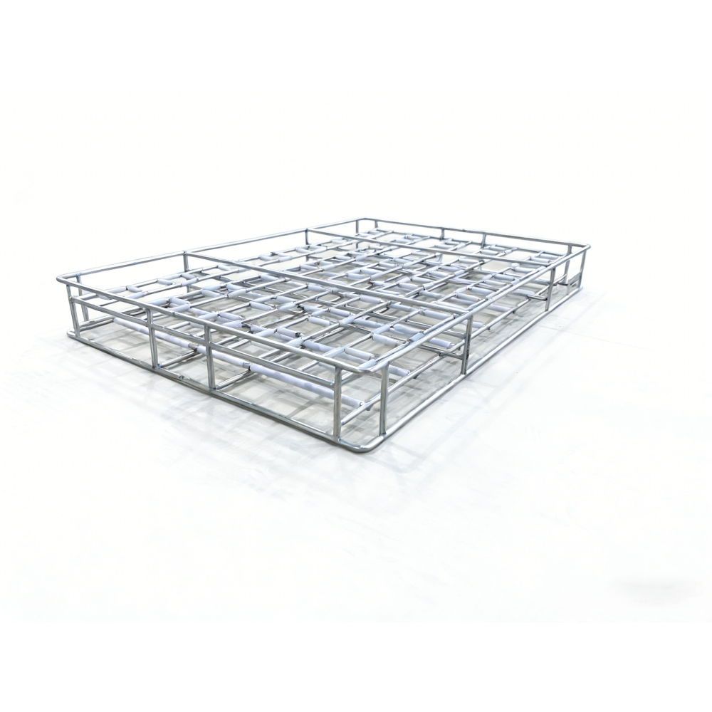
Hold gear shafts upright in a welded tray designed around their contact points. Teflon sleeves, a matching lid and stackable frames bring part protection and handling into the same design.
Gear shafts need more than enough space in a cleaning basket. They also need to stay in the position required by the cleaning process, without unnecessary contact with neighbouring parts or bare metal.
This AUKE welded wire tray holds gear shafts upright in locating positions lined with Teflon sleeves. A matching hold-down lid presses against the tops of the shafts to help keep them in place. The fixed layout gives each shaft a defined position, while the sleeves separate it from exposed metal at the covered contact points.
The trays can also be stacked for storage, loaded handling and cleaning inside the machine. For a custom design, shaft spacing and frame height therefore need to work together: the arrangement must accommodate the parts within each tray and leave suitable clearance between loaded layers.
Each gear shaft is lowered vertically into a locating position lined with Teflon sleeves. The surrounding rods limit sideways movement, while the matching lid presses against the top of the shaft. These features work together to help maintain the required orientation during handling and cleaning.
The locating space needs to suit the shaft’s profile. Too much clearance can allow unwanted movement; too little can make loading difficult or bring the shaft into contact with areas that should remain clear. The lid also needs to match the shaft height so that it holds the part without forcing it into the tray.
For a custom AUKE tray, we can position the sleeved rods around the shaft geometry and the surfaces permitted to touch the fixture. Once welded, those locating positions remain fixed, giving operators a defined loading arrangement without having to reposition individual supports between batches of the specified part.
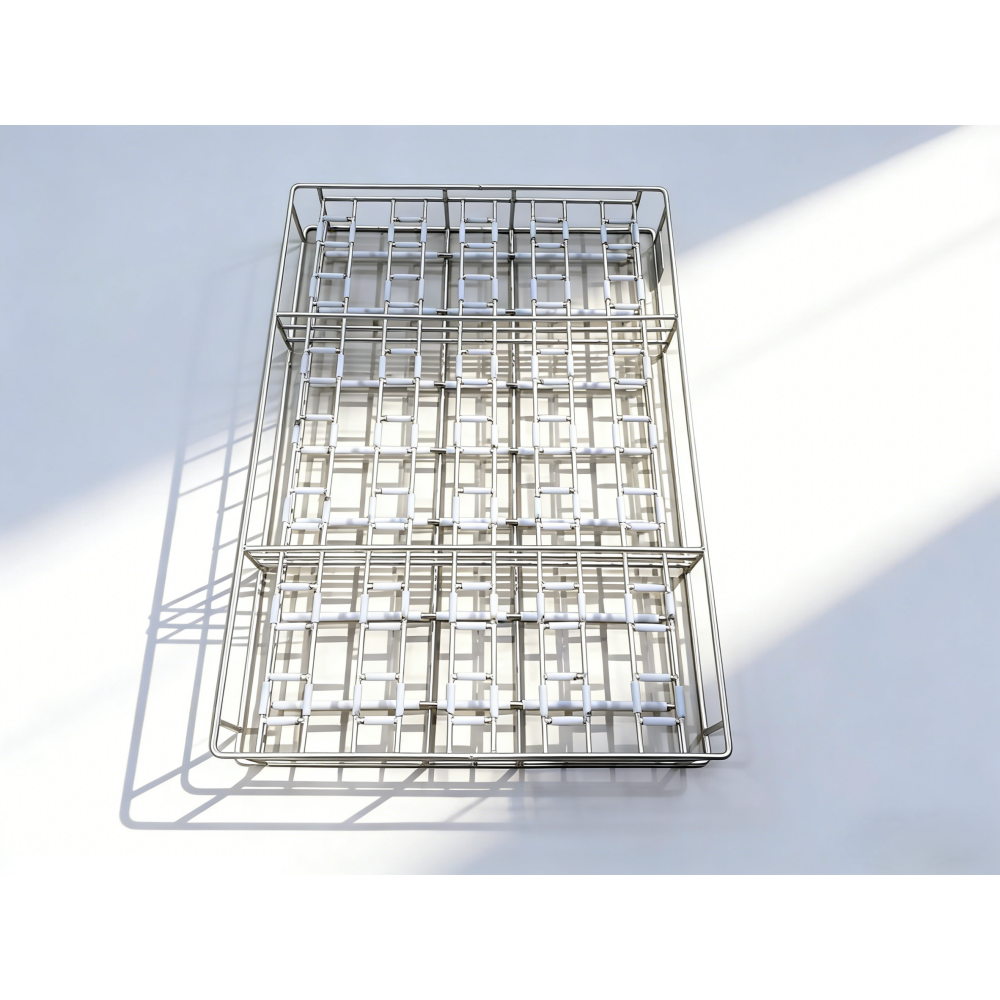
The empty tray shows the fixed locating layout. The shaft profile determines which sleeved surfaces it may contact.
The locating rods need to keep the gear shaft in position, but their contact surfaces also matter. AUKE fits Teflon sleeves over the rods at selected locations, separating the shaft from bare steel where contact is intended.
The sleeve positions should follow the shaft profile, not simply cover every available rod. A shoulder, a toothed section and a finished shaft surface may have different contact restrictions. We can use the customer’s drawing to identify where the tray may touch the part and where clearance needs to remain.
This makes the sleeves part of the locating design rather than an added covering. They change the contact surface; they do not correct a poorly positioned rod or an overly tight fit. The aim is to support the required upright arrangement while avoiding unnecessary metal contact and leaving the surfaces that need cleaning accessible.
You can also explore AUKE’s custom wire baskets with Teflon-sleeved contact surfaces to see related construction options.
Different features, different jobs: the locating rods limit sideways movement, the sleeves separate selected contacts from bare steel, and the lid helps hold the shafts in place from above.
Placing gear shafts upright gives them a defined orientation, but it does not by itself ensure that every surface will be cleaned. The distance between shafts and the position of the surrounding rods still determine how much space remains around each part.
The welded wire structure leaves openings around the locating positions. When choosing the shaft spacing, we need to preserve access to the surfaces being cleaned rather than fit as many parts as possible into the tray. Closely packed shafts or poorly placed supports can obstruct that access, even when every part sits securely.

SPACE BETWEEN LOADED LAYERS
Stacking adds another dimension to the layout. The frame height must accommodate the shafts and their lid while leaving suitable space between loaded layers. An upper tray should not press on the shafts below or interfere with the intended lid arrangement.
This view shows the empty frame and open construction, not a loaded stacking arrangement.
For AUKE, shaft spacing and stacking height are therefore part of the same design discussion. The usable load is the arrangement that fits the machine and meets the required cleaning result, not simply the largest number of shafts that can be placed inside the frame.
AUKE generally recommends 304 stainless steel as the starting material for this welded tray, with other grades available to suit the application. The final choice depends on the cleaning medium and operating conditions, not simply on the fact that the parts are automotive components.
The Teflon sleeves need to suit the same process. Cleaning temperature is only one consideration: the drying stage, exposure time and contact load also matter. A material that tolerates a given temperature is not, by that fact alone, suitable for every cleaning chemical or loaded assembly.
For an ultrasonic or hydrocarbon cleaning application, we would use the equipment manufacturer’s process requirements to discuss the tray materials and configuration. This keeps the specification tied to the customer’s actual cleaning cycle rather than assigning one temperature range to every tray.
The overall size of a gear shaft does not tell us where it can safely touch the tray. Your drawing helps us identify the shaft profile, the surfaces that need clearance and the positions available for sleeved supports.
Share the drawing with AUKE, along with any surfaces that must not be touched. We can discuss the locating gaps, Teflon sleeve positions and how the lid should meet the top of each shaft. If you also have the cleaning machine’s basket dimensions, we can consider shaft spacing and stacking height within that space.
You do not need to design the tray first. Start with your gear shaft drawing; our wire basket customization requirements outline the material, dimensions and application details we can discuss with you.
Possibly, but similar outside dimensions do not guarantee the same fit. Shaft profiles, permitted contact surfaces and overall heights need to be compared. Send AUKE the drawings of the shafts you want to accommodate, and we can discuss whether one fixed layout is practical or separate trays would be more suitable.
There is no single stacking limit for every configuration. The number depends on the loaded tray weight, frame design, shaft and lid height, and the machine’s available space and load limit. The proposed stack also needs to leave sufficient access for the cleaning process.
Not necessarily. Sleeves are placed where the design calls for separation between the shaft and bare metal. Covering rods that do not contact the part may offer little benefit. The shaft drawing and permitted contact areas help determine where sleeves are useful.
Send the gear shaft drawing and identify any surfaces that must not be touched. If available, include the machine’s basket dimensions, load limit and cleaning conditions. You can start with the information you already have; we can clarify the remaining requirements during the discussion.
Send AUKE your gear shaft drawing and tell us what the current basket makes difficult: keeping shafts upright, avoiding unwanted contact or fitting a loaded stack into the machine.
We can use those details to discuss the fixed locating layout, Teflon sleeve positions and matching lid. For a new project, the shaft drawing is enough to begin the conversation; machine dimensions and process requirements can follow as we develop the tray specification together.
Email Your Gear Shaft Drawing to AUKEPrefer to discuss the application first? Contact AUKE about your gear shaft cleaning tray.