Views: 58 Author: Lucian Publish Time: 2026-09-01 Origin: Site


A process engineer usually receives two sets of dimensions: the part load and the cleaning machine chamber. The basket must carry the loaded parts through the complete machine route, not merely sit inside the chamber. A simple box comparison misses the door opening, guide rails, support ledges, spray hardware, gripper access and the path used to turn the basket into position.
The result can be a finished basket that holds every component but cannot be loaded without tilting, scraping or removing a handle. That means rework, delayed production and an operator workaround that was never part of the intended process. Reliable industrial cleaning basket dimensions begin with the interface, not the nominal chamber volume.
THE FIT GATE
The basket must pass the narrowest point, seat on the intended supports and complete its operating movement while loaded. Passing only one of those conditions is not a fit.
A cleaning machine data sheet may state a useful chamber size or standard basket size. Those values are essential, but they do not describe the complete insertion route. The basket may approach through a smaller door, cross a seal frame, pass between nozzles and then drop onto rails that are narrower than the chamber.
Loading orientation changes the comparison again. A basket inserted lengthwise may clear the door but require a turn inside the machine. The swept corner during that turn occupies more space than the final parked position. If the operator has to lift one side to make the turn, the loaded weight and part retention also enter the decision.
APPLICATION EVIDENCE
The image shows a custom basket sitting on a machine interface. The relevant dimensions are not limited to its outside walls. Base runners, frame corners and the position of the load relative to the support all affect whether the basket sits level and remains stable.
A small mismatch at the base can shift the load, obstruct movement or place weight on mesh that was not intended to carry it.
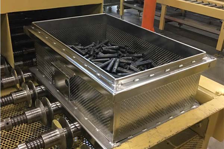
A useful cleaning-machine fit drawing separates the dimensions by function. Combining everything into one maximum size hides which feature is allowed to move and which surface must carry the load.
This separation also clarifies responsibility. The cleaning machine drawing defines the available envelope and support points. The basket drawing defines the maximum manufactured envelope and permitted motion. The interface sheet connects the two with stated clearances and loading orientation.
A folded handle may sit within the basket footprint yet swing beyond it during lifting. A lid may add little closed height but need overhead room to open. A latch can catch a door seal or adjacent basket even when the main frame has generous clearance.
Cleaning basket handle clearance therefore needs two views: the handle at rest and the full lifting position. The drawing should also show where an operator's hand, hoist hook or automated gripper approaches. A dimension that leaves no access is technically open space but not usable space.
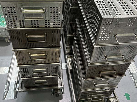
The basket bodies may be similar, while the fixed and folding handles create different maximum widths and grip positions. Those projections matter at the cleaning machine door, during stacking and on the transfer trolley.
Specify the handle condition for every stage instead of treating it as an accessory added after the basket size is fixed.
A chamber photograph is helpful, but a photograph alone cannot establish clearance. AUKE works from a cleaning machine drawing when available and supplements it with measurements taken at the real loading path. We identify the limiting edges before defining the basket maximums.
Door clear width and height, seal frame, threshold, loading table height and the direction in which the basket approaches.
Rail spacing, ledge width, nozzle location, chamber height over the loaded part and any oscillation, rotation or lift stroke.
Trolley deck, conveyor guides, fork or gripper access, stacking stops and the height at which the loaded basket changes support.
The required clearance should be agreed at each limiting location. It depends on machine movement, fabrication tolerance, thermal conditions, loaded deflection and how accurately the handling system places the basket. A single universal clearance value would hide those differences.
Start with the limiting path
Send the cleaning machine drawing, a front view of the door and rails, basket loading orientation, loaded weight, and handle or lid requirements. We will map the limiting interfaces and list the missing dimensions before a basket concept is fixed.
The approved maximum is only useful if production stays inside it. Wire diameter and mesh opening affect the basket body, but the critical interface often sits in the frame. Cut length, bending position, weld sequence and heat input can shift the final length, pull runners out of parallel or change the lid height.
We define the critical dimensional points on the basket drawing, measure the completed frame after welding and record the handle and lid in their limiting positions. A fixture can hold runner spacing or frame squareness during welding when those features locate the basket on the machine.
Loaded weight also changes the load path. If the base deflects between support rails, the effective clearance below the basket decreases. Reinforcement may control that movement, but its position cannot block a nozzle, drain path or loading feature. Strength and fit therefore have to be resolved on the same interface drawing.
Before repeat production, AUKE runs the proposed basket through the defined handling sequence with a representative load whenever the customer can provide the machine or an accurate interface fixture. We record the basket orientation at entry, support contact after seating, handle and lid movement, and the path used for removal.
The trial is intended to expose assumptions that two-dimensional drawings can miss. A gripper may need approach room. A folding handle may fall toward a seal. A trolley stop may contact the basket before its runners reach the machine rails. Each finding points to a specific dimensional correction instead of broad rework.
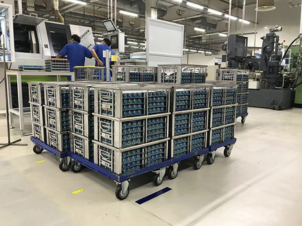
Cleaning machine fit is only one interface. Basket width, handle position and base support also need to remain compatible with the transfer method used before and after cleaning.
Once the loaded path is accepted, the drawing retains the critical industrial cleaning basket dimensions, tolerance direction, loading orientation and support locations. Those controlled values give later production orders a repeatable basis rather than relying on the first sample as an unmeasured reference.
No. The door opening, insertion route, support rails, internal equipment and operating movement may provide less space than the chamber itself.
Yes. State the maximum resting position and the full lifting position. Both can interfere with the cleaning machine, trolley, adjacent basket or operator access.
Record the rail center or edge references, usable ledge width, height difference and any obstruction between them. The basket drawing should use the same reference points.
Send the cleaning machine drawing, door and rail measurements, loading orientation, basket quantity, loaded weight, part envelope, handle and lid needs, and transfer method.
Confirm the interface before fabrication
Share the cleaning machine drawing, loading photographs, basket orientation, loaded weight and moving-feature requirements. We will identify the limiting path, define the required interface dimensions and propose which conditions belong in the loaded fit trial.
Request Machine-Fit SupportBy AUKE Engineering Team